Learning Assembler via Floor Anthoni’s PDP-8 Cookbook
At the Medical Biological Laboratory I was responsible for the Electronics Department, serving all other departments. Early computers of the DIGITAL PDP8 family prompted me to study computer operating systems and to set down the design parameters for modular design.
DECUS ET TUTAMEN
Floor Anthoni“Born Johannes Floris Anthoni, nicknamed Floor (these names are an Anthoni family tradition, bestowed on the eldest son)”
finished out his Dutch military service in the 1960s with a stint at the Dutch national defence research organisation, and stayed there for 10 years. While he worked there, he compiled a number of examples of good modular PDP-8 assembler code.
In early 1972, he asked DEC User Society members to submit code examples for him to collate and publish:
In programming the PDP8 computer. I have experienced the usefulness of program modularity at the assembly level. The basic modules are, in effect, subroutines that perform a certain function, and that have been programmed in such a way, that they can be used as “recipies” in a cookbook. When these “recipies” are being sent to a central editor, and published regularly, they will accumulate experience into a common module library, THE PDP8 COOKBOOK, available to others.
In 1973 he published his first set of example codeAll of which were submitted by researchers at Dutch laboratories.
as DECUS document No. 8-602A, and reproduced his call for submissions in the Introduction.
Subroutines
The subroutine jump certainly is the most powerful instruction of any computer. It enables the programmer to avoid duplication of code, and to build hierarchical structures of software intelligence, increasing the semantic power of each free location in core.
The PDP-8And thus, the PDP-12, which is both a PDP-8 and a LINC processor in one cabinet.
has a primitive form of subroutine call built right into its very tiny instruction set. There is no support for recursion, and programmers are required to manage by hand how each subroutine will pass information in and out. To address this, Floor decided to set some standards:
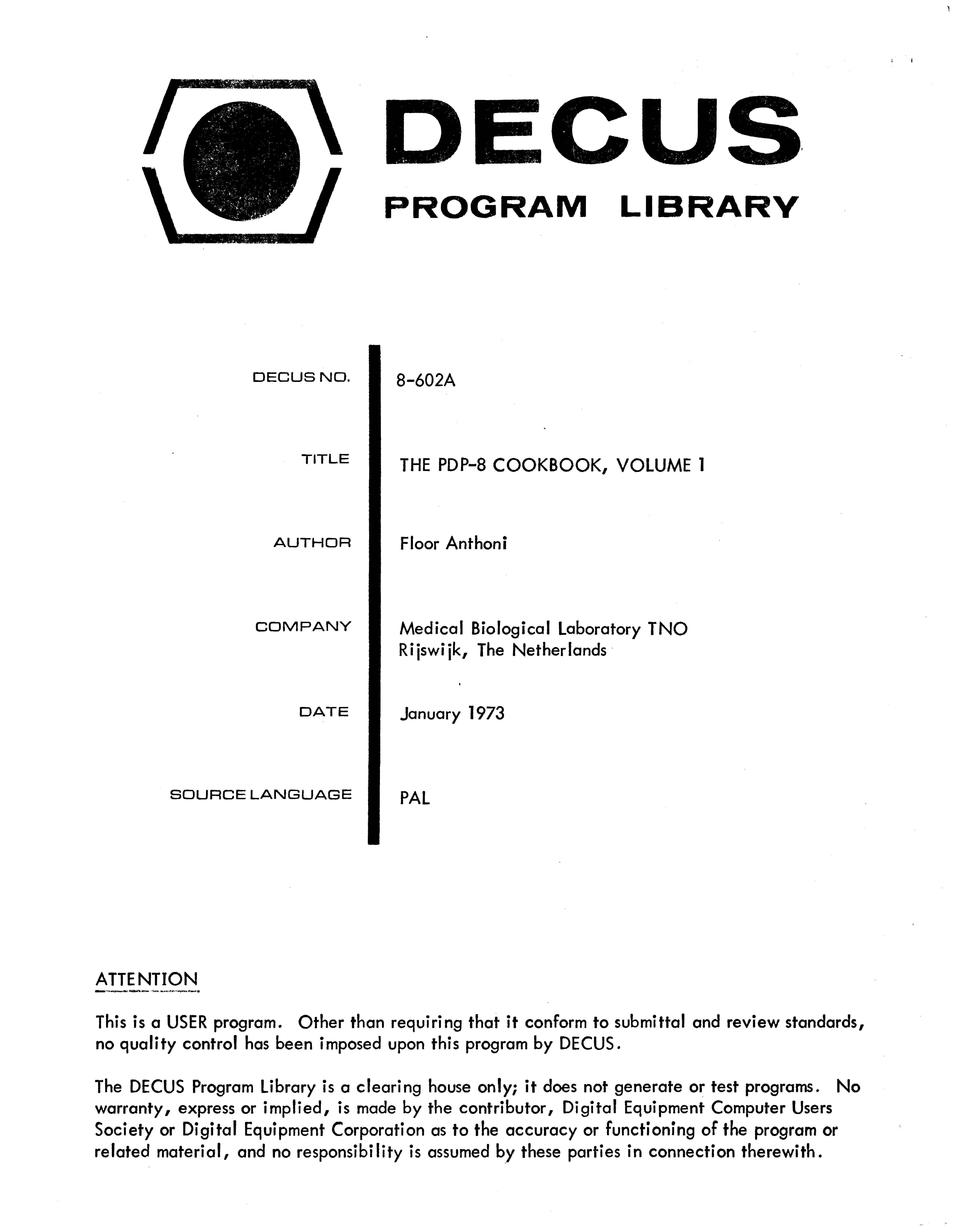
When only one parameter needs to be transferred, use the ACCUMULATOR. The LINK can be used as additional YES or NO information, although it is, in general not frequently used. The use of other registers, like the MULTIPLIER-QUOTIENT register, must be strongly dissuaded, because the module will then not be able to run on many machine configurations.
More information can be transferred as arguments, following the JMS instruction. This is especially useful for parameters that can be set at assembly time, or that need not to change very often. Use the AC for frequently changing information. A common information area in page 0 can also be used. This is especially useful when those parameters need to be accessed by many modules.
Modern practice is to call the least-significant bit “0” and count up as we move left. For some reason, Digital always counted in the other direction. Take care when interpreting bit numbers described in DEC manuals!
We will investigate the details of some of these approaches later on in this document. Let’s jump right in.
We’ll break it down into pieces as we go, but to start with here’s the entire listing.I have written some syntax highlighting rules that should cause code examples to appear here with font styling applied.
Comments are in italics, PDP-8 instructions and PAL operators are bold, assembler directives and labels are underlined, and unknown opcodes (which may or may not be errors) are in reverse video.
/001 TYPE THE CHARACTERS FOLLOWING THE JMS INSTR./TERMINATOR IS A ZERO.// JMS TYPTEX /TYPE "ABC"/ 301 /"A"/ 302 /"B"/ 303 /"C"/ 0 /TERMINATOR/ RETURN /AC=0TYPTEX,0TADI TYPTEX /GET CHAR.ISZ TYPTEXSNA/ZERO?JMPI TYPTEX /YES,JMP TO NEXT LOC.JMS TYPE /NO,TYPEJMP TYPTEX+1
Comments
In PAL, the standard PDP-8 assembler, everything following a / is a comment. Floor began this section with the entry number (001) and a brief description of how to use this subroutine. Following that, he gave some example codeComplete with explanatory comments-within-comments!
so you can see how this might be used:
Use the JMS instruction to call TYPTEX.
Put the characters you wish to type out after this instruction in your code.
When you do not wish to print any more characters, insert a 0 in your code.
The example also mentions that the ACCUMULATORAC for short.
will be set to 0 when TYPTEX returns.
So let’s start with each of these parts in turn:
JMS vs JMP
The JMS instruction stands for “JuMp to Subroutine”. It takes one argument, which in PAL is most likely a label that the assembler will translate into the appropriate address where the code for the subroutine can be found.
JMS then does two things:
It writes the address of the instruction after itself into the location you pass to it.
It then causes the computer to run the next instruction after the address of the subroutine you gave it.
What this means is that all subroutines on the PDP-8 begin not with code, but with a return address. When your subroutine is finished, you can use the JMP opcode to JuMP back to the code that called it and resume normal operation.
Raw numbers
You’re likely familiar with higher-level programming languages where variables and code are clearly marked out. But when writing PAL assembler, we often insert raw numbers into the stream of instruction words.
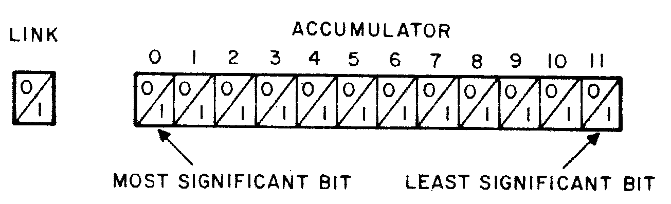
Since the PDP-8 is a 12-bit machine with binary switches on the front, programmers tended to think of values in groups of four octal digits. PAL defaults to using octal notation for all raw numbers, and you can leave off any leading zeroes.
So how do we get that 301 is "A"? If you look at your ASCII table, you should see that A is listed as 101 in octal. But the difference between 1 and 3 in base 8 is the flipping of a single bit, so this is effectively an ASCII A with the high bit set.Introduction to Programming PDP-8 Family Computers says:
Channel 8 is normally designated for parity check. The Teletype units used with PDP-8 series computers do not generate parity, and Channel 8 is always punched.
So we insert the values for A, B, and C into the instruction stream with the high bit set on each, and then the 0 that we were informed would indicate the end of the string to be printed.
But that leaves an interesting question: wouldn’t the TYPTEX subroutine JMP back to the location after we called it, which is data rather than code? Shouldn’t that cause bizarre unpredictable behaviour? To answer that, we need to look at the subroutine code itself.
TYPTEX, 0
The very first part of the subroutine is the label, which gives a name to the routine’s location in core.An archaic term for RAM: the PDP-8’s memory was made of tiny ferromagnetic rings called “cores” long before semiconductor RAM was available. Magnetic core memory has the advantage that it provides long-term storage long after the power is shut off.
Everywhere we put TYPTEX in as a symbol, PAL will replace that with the real address in whatever format is necessary.
And just as with the arguments that followed the JMS when we tried to use this subroutine, we’ve just put a raw 0 there. That is simply a placeholder for the return value that JMS will insert when this routine is called.
TAD I TYPTEX
The very first instruction loads data into the ACCUMULATORAgain, also called AC
This means that we probably should have ensured the ACCUMULATOR was zero first.
So what does it load? Well, you can see that it’s doing something with TYPTEX, which is the location that holds the return address for us to JMP back to. The I indicates that it is reading that address in memory-indirect mode. This means that it will use the address stored in TYPTEX to load the value to use.
Put another way, TYPTEX will be used as a pointer to the actual word in memory. At the start of our example invocation, that means it will load the octal 301 value that represents the A and add it to the ACCUMULATOR(AC)
.
So it seems we have loaded our first argument! But using the same value for data and the return address still seems wrong, doesn’t it? Well let’s proceed.
ISZ TYPTEX
Once we’ve loaded the A, we run the “Increment and Skip if Zero” instruction. Since we don’t expect these addresses to overflow back to zeroAt least, PAL would have done a very bad job if they do!
, this can just be taken as incrementing TYPTEX.
So now we have read the value at the return pointer, and incremented that pointer to the next word. If we keep this up, we should move past all of the data and back into code!
SNA
The SNA instruction is one of the “microcoded”Not microcoded in the modern sense, as in a CPU that runs an even tinier code engine inside, but rather an instruction where instead of an operand it takes combinations of bits to join circuits together inside the CPU to generate a composite operation.
OPR instructions that work only on the registers, and it stands for “Skip on Non-zero Accumulator”. Since our AC contains octal 301, that is non-zero, and we skip the next instruction. So let’s look at the one after it.
JMS TYPE
Since we skipped the previous instruction, we now JMS to a subroutine called TYPE, which we will look at in the next chapter. We don’t need to know too much about how it works now, but we can assume from the rest of TYPTEX that it prints whatever character is in AC and clears AC to 0 before returning.
So we’ve just printed the A, but how do we get to the B from here?
JMP TYPTEX+1
Since the TYPTEX label points to the address of the combined argument pointer/return address word, we can re-start the subroutine by JMPing to the address immediately after that. So let’s look at each loop now and take particular interest in that SNA instruction.
Loop Analysis
So here are the iterations through TYPTEX for the example invocation the comments:
AC loaded with "A", which isn’t zero so SNA skips to JMS TYPE and it is printed.
AC loaded with "B", which isn’t zero so it gets printed.
AC loaded with "C", which isn’t zero so it gets printed.
AC loaded with 0, which is zero, so SNA doesn’t skip.
So what is the instruction we kept skipping?
JMP I TYPTEX
Every time we’ve consumed an argument, we’ve incremented the address stored at TYPTEX, so that it pointed to the next location in the example code. Well by now since we’ve consumed the 0, we’ve run out of the non-code data in that section of the program, and can return back to it by doing a memory-indirect JMP to it.
So as a reminder, this means “Load the number at TYPTEX, and then jump to the instruction stored at that number.”
So now we’ve printed each of the letter arguments, stopped at 0, and returned with a clear AC. Sounds great!
But now, how did that TYPE function work?
TYPE
/002 TELETYPE TYPE ROUTINE/INITIALIZES WHEN ENTERED FOR FIRST TIME./NOT RESTARTABLE !// TAD CHARACTER/ JMS TYPE/ RETURN /AC=0NOPTYPE,0JMP.+3/OVERLAID BY "NOP"TSFJMP.-1TLSCLATAD TYPE-1DCA TYPE+1JMPI TYPE
This seems to have a simpler set of instructions for use in the comments:
Load a character into AC
JMS to this routine
AC will be zero when we return
So let’s start looking at the code.
NOP
This is an oddity. For a start, NOP is the “no-operation” instruction.Sometimes written “NOOP”.
It’s implemented in nearly all computer architectures, and it’s significant for the fact that it does…exactly nothing. When the CPU hits a NOP, it will waste a bit of time fetching and decoding the instruction, but it then just skips ahead to the next instruction.
As a second oddity, this do-nothing instruction has been placed before the function we wish to call, making it a useless opcode at a location we don’t expect to execute.
Let’s remember this and move on to the next bit.
JMP .+3
After setting up the traditional 0 placeholder for TYPE’s return address, we see a new trick that PAL lets us do.
The symbol . refers to the address of the current instruction, so we can do basic arithmetic on that to refer to memory addresses a short fixed distance away. In this case, we’re skipping ahead three instructions. We’ll need to puzzle out why,This sort of quick arithmetic isn’t always clear to the reader, and there’s no hint for the reasoning behind those addresses, so it’s often better to use explicit labels on the instructions you want to jump to. However, Floor expressed a concern in his standards document that adding too many symbols increases the chance that labels will appear twice, crashing PAL. With that in mind, this approach is understandable.
so let’s jump ahead, but first let’s think about that comment:
/OVERLAID BY "NOP"
The puzzles are compounding. A do-nothing instruction in a never-runs part of memory is expected to “overlay” this JMP somehow? Let’s set that aside and press on.
TLS
Skipping ahead three instructions, we find that we’re in one of the IOT opcodes, which concern themselves with device I/O.IOT stands for In-Out Transfer.
In this case, the PDP-12 Reference Manual describes the effect of TLS as:
Clear the printer flag, transfer the contents of the AC into the printer buffer register, select and print the character. (The flag is raised when the action is completed.)
So this instruction will set some “printer flag” bit to 0 somewhere in the hardware, print out whatever is in AC, and then set that “printer flag” to 1 to let anyone who’s interested know that the printer is ready to print another character. So I guess we’ve just printed our character!
There’s a lot of code in here for a subroutine that seems to mostly be handled by this one instruction. What does the rest of this thing do?
CLA, DCA, and Clues to the NOP Mystery
CLATAD TYPE-1DCA TYPE+1JMPI TYPE
The first three instructions are a fairly common idiom, with two new instructions for you to learn:
CLA is simply “CLear Accumulator”, which sets AC to 0.
Then we use TAD to add the value at TYPE-1 to the empty AC. This is that NOP instruction.
DCA is “Deposit and Clear Accumulator”, which we use to write that NOP instruction to TYPE+1.
Aha! So this copies that NOP from the pre-subroutine address over the JMP .+3 instruction. Now at least we see what the comment meant by /OVERLAID BY "NOP". But why? We do this and then return from TYPE using the JMP I instruction as before.
Second Time Lucky
let’s take a look at what the subroutine looks like now, and see if we learn anything by tracing it again:
NOPTYPE,0NOP/OVERLAID BY "NOP"TSFJMP.-1TLSCLATAD TYPE-1DCA TYPE+1JMPI TYPE
So now when we call our function with the second character, it hits that NOP instead of JMP .+3, and just glides down to the next instruction, which is one we haven’t executed yet.
TSF
This is another IOT instruction for the printer, and the PDP-12 Reference Manual describes it as:
Skip the next instruction if the printer flag is set to 1.
If you recall, the TLS instruction we ran last time set that flag to 0 while it was busy printing, and set it to 1 to show that it was done. Let’s assume that our program is extremely fast right now, and gets back here while all the motors and gears are still turning on our printer, and the flag is still 0. That means we don’t skip, and just run the next instruction.
JMP .-1
There’s the relative-jump arithmetic again. This just jumps back to that TSF instruction every time until it’s skipped. So these three instructions together create a “print when ready” macro:
TSFJMP.-1TLS
So why didn’t we do this in the first place? Why spend all of this memory and time copying NOP instructions around and doing funny JMPs?
The Trouble With TSF
The problem with this printer flag is that we only know it’s correct if we’ve already printed at least one character after turning on all of our equipment. When the hardware first powers on, it’s set to 0 by default. So this is what the comments meant at the start:
/002 TELETYPE TYPE ROUTINE/INITIALIZES WHEN ENTERED FOR FIRST TIME./NOT RESTARTABLE !
We needed to at least try to print a character the first time, or that TSF/JMP .-1 loop would spin forever.
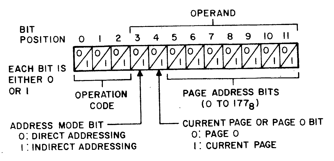
PDP-8 Instructions
So far we’ve encountered seven of the eight opcodes on the PDP-8. These are represented in memory as the most significant three bits of an instruction word.There is a pleasing sort of symmetry to this: Two instructions read from memory, two write to memory, two modify the program counter, and two don’t touch memory at all.
The eight PDP-8 opcodes.
Instruction
Opcode
Name
Cycle count
AND
0nnn
logical AND
2
TAD
1nnn
2’s complement add
2
ISZ
2nnn
increment and skip if zero
2
DCA
3nnn
deposit and clear AC
2
JMS
4nnn
jump to subroutine
2
JMP
5nnn
jump
1
IOT
6nnn
in-out transfer
2 1/2
OPR
7nnn
operate
1
Memory-addressing Instructions
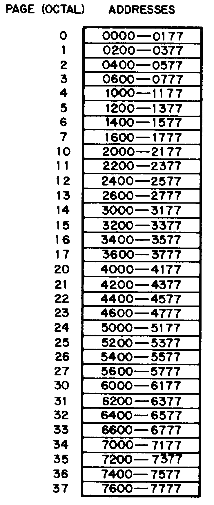
The first six instructions use the other nine bits to indicate a memory location, but in a limited way. The bottom seven bits are the location of the operand within a “page” of memory, which is a region of only 128 words. The eighth bit determines whether the address is in the “current” page, where the code currently lives, or on page zero.Since you can operate on values in the zero page from any code, it tends to be a sort of “global variable area”. Floor explicitly tries to avoid using it, for the same reason he avoids adding too many labels: he doesn’t want to conflict with the rest of your code.
So far, we’re able to directly address only 256 words out of the 4096 you can address with a 12-bit pointer. So what gives? Well that’s where the memory-indirect bit comes in. If it’s set highRemember that’s done with the I as in JMP I TYPE.
then we use that word as a full 12-bit pointer to the actual word we want to load and use.
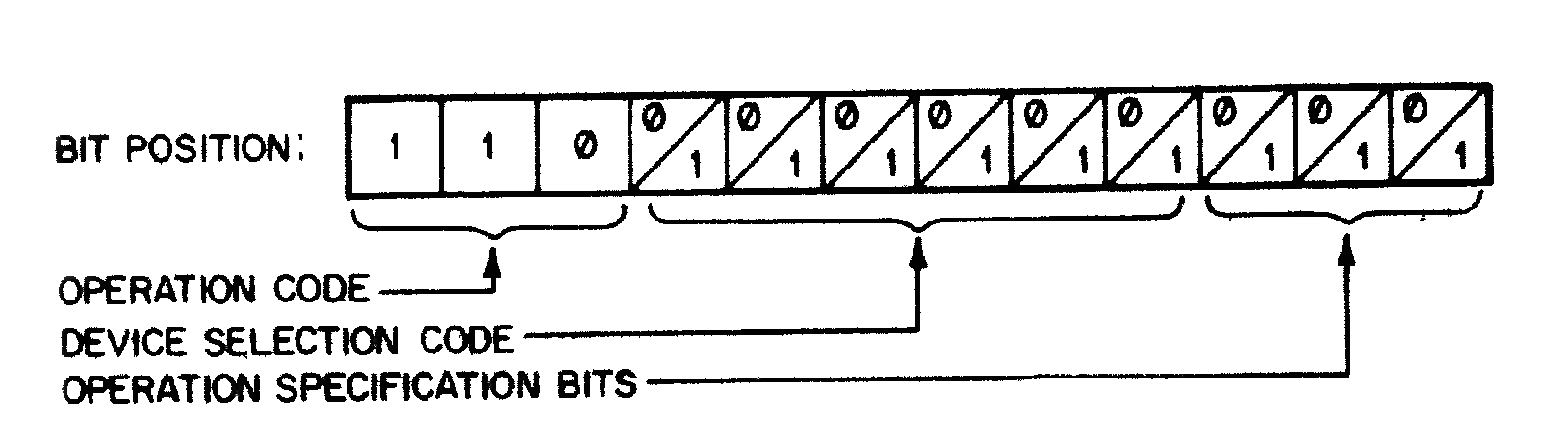
IOT
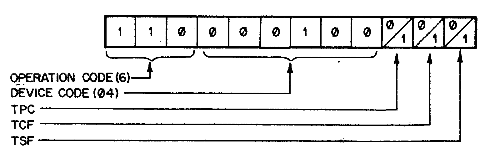
The IOT instructions are more specific. The middle six bits indicate which device to connect to, and the last three bits form an instruction to send to that device.
As an example, we saw in TYPE that device 04 was the teletype printer. Here’s what the PDP-12 Reference Manual says in full about the use of the last three bits:Note that TLS is just the logical outcome of setting both the TCF and TPC bits.
Teletype Printer/Punch Instructions
Sequence
Mnemonic
Octal
Effect
1
TSF
6041
Skip the next instruction if the printer flag is set to 1.
2
TCF
6042
Clear the printer flag.
3
TPC
6044
Load the printer buffer register with the contents of the AC, select and print the character. (The flag is raised when the action is completed.)
2,3
TLS
6046
Clear the printer flag, transfer the contents of the AC into the printer buffer register, select and print the character. (The flag is raised when the action is completed.)
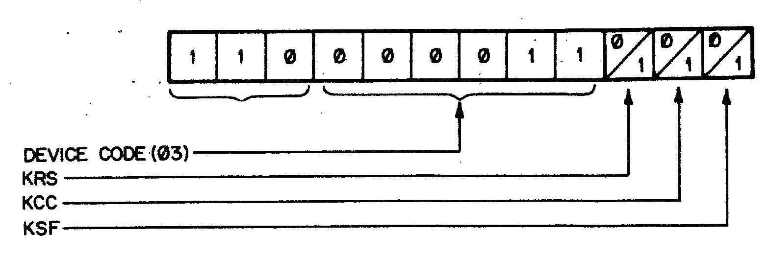
For comparison, take a look at the keyboard input side of the teletype, which is device 03.
Teletype Keyboard/Reader Instructions
Sequence
Mnemonic
Octal
Effect
1
KSF
6031
Skip the next instruction when the keyboard buffer register is loaded with an ASCII symbol (causing the keyboard flag to be raised).
2
KCC
6032
Clear AC, clear keyboard flag.
3
KRS
6034
Transfer the contents of the keyboard buffer into the AC.
2,3
KRB
6036
Transfer the contents of the keyboard buffer into the AC, clear the keyboard flag.
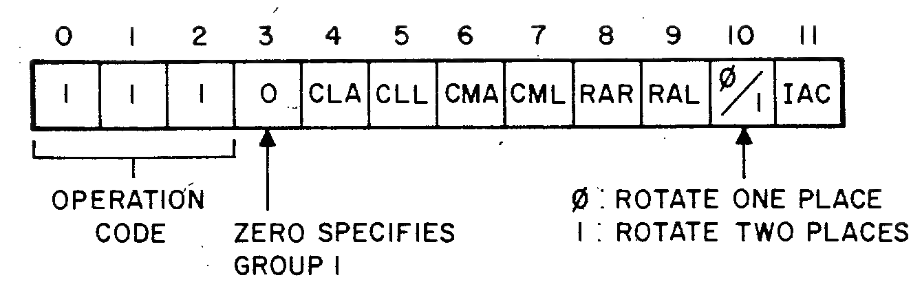
OPR
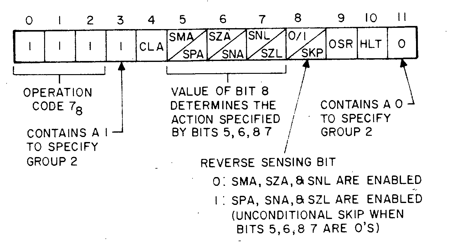
The OPeRate instructions also use the lower nine bits to indicate actions you can combine. None of these operations affect memory, although several will skip the next instruction if certain conditions are met. All of these operations take one cycle, but the component sub-operations have an implicit order. Of the nine remaining bits, the most significant one switches between “Group 1” and “Group 2” operations.
Group 1 OPR Micro-instructions
Mnemonic
Opcode
Name
Event Time
NOP
7000
No Operation
0
CLA
7200
clear AC
1
CLL
7100
clear LINK
1
CMA
7040
complement AC
2
CML
7020
complement LINK
2
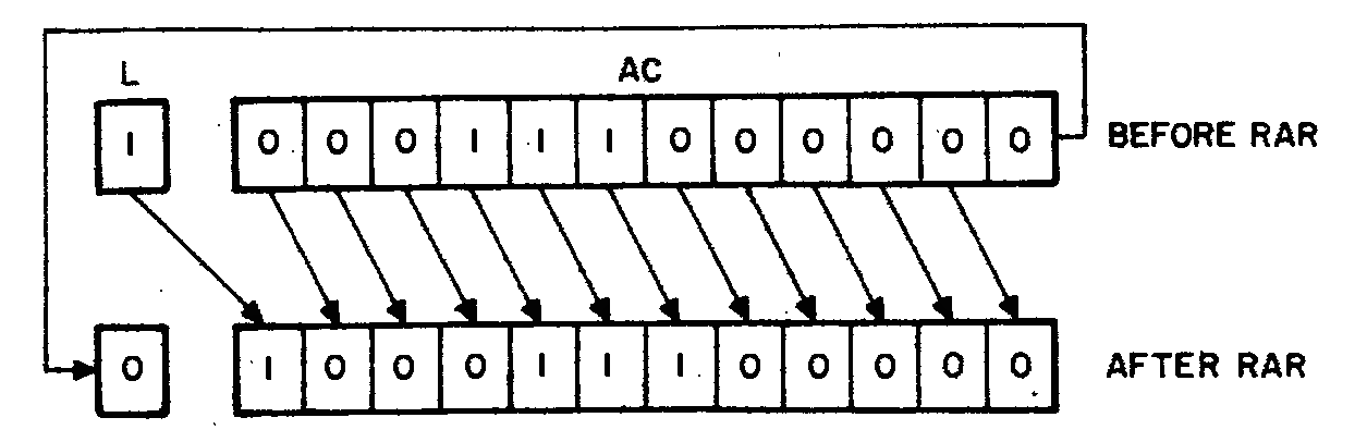
RAR
7010
rotate AC and LINK right one
4
RAL
7004
rotate AC and LINK left one
4
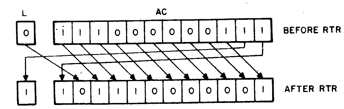
RTR
7012
rotate AC and LINK right two
4
RTL
7006
rotate AC and LINK left two
4
IAC
7001
increment AC
3
Group 2 OPR Micro-instructions
Mnemonic
Opcode
Name
Event Time
SMA
7500
skip on minus AC
1
SZA
7440
skip on zero AC
1
SPA
7510
skip on plus AC
1
SNA
7450
skip on non zero AC
1
SNL
7420
skip on non-zero LINK
1
SZL
7430
skip on zero LINK
1
SKP
7410
skip unconditionally
1
OSR
7404
inclusive OR, switch register with AC
3
HLT
7402
halts the program
4
CLA
7600
clear AC
2
Any instructions from the same group can be combined and still take only once cycle. For example, you can quickly load a number of constants into the AC in one instruction made of Group 1 Micro-instructions.A word of warning, however: older PDP-8 models such as the original “Straight 8” or the LINC-8 (a predecessor to the PDP-12!) won’t allow mixing IAC with the rotation instructions (RAL, RTL, or RTR). It’s possible Flor Anthoni couldn’t have generated literal 3, 4, 6, or 6000 this way!
Quick Constant Instructions
Octal
Combination
Result in AC
7201
CLA IAC
0001
7326
CLA STL RTL
0002
7325
CLA STL IAC RAL
0003
7307
CLA CLL IAC RTL
0004
7327
CLA STL IAC RTL
0006
7344
STA CLL RAL
7776 (-2)
7346
STA CLL RTL
7775 (-3)
7330
CLA STL RAR
4000
7332
CLA STL RTR
2000
7333
CLA STL IAC RTR
6000
TYPTEX, Redux
Printing text that’s in our code is all well and good, but what about other strings in memory? Can we rewrite TYPTEX to accept a pointer?
/003 TYPE A CHARACTER CHAIN/TYPE THE CHARACTERS IN THE LIST, POINTED TO/BY THE FIRST ARGUMENT. LIST TERMINATOR =0// JMS TYPTEX /TYPE "ABC"/ LIST/ RETURN /AC=0//LIST, 301/ 302/ 303/ 00/USED AS POINTERTYPTEX,0/TYPE TEXTSTRINGTADI TYPTEX /GET ARGDCA TYPTEX-1/SAVE TO USE AS POINTERISZ TYPTEX /FOR CORRECT RETURNTADI TYPTEX-1/GET CHARSNA/ZERO?JMPI TYPTEX /YES, RETURNJMS TYPE /NOISZ TYPTEX-1JMP TYPTEX+4/LOOK FOR NEXT
We pass in only one actual argument, which is the pointer to the null-terminated string in memory.We could just as easily have passed this via the AC per Floor’s standards. That is left, as they say, as an interesting exercise for the reader.
So let’s take a look at the pieces.
Locals, args, and return address
0/USED AS POINTERTYPTEX,0/TYPE TEXTSTRINGTADI TYPTEX /GET ARGDCA TYPTEX-1/SAVE TO USE AS POINTERISZ TYPTEX /FOR CORRECT RETURN
We’ve seen all of this before. The only novel thing here is that the address before the start of the subroutine is being used as a local copy of the argument instead of a constant. We will see TYPTEX-1 used throughout the rest of this code to refer to our “local variable”.
Loop over TYPE
TADI TYPTEX-1/GET CHARSNA/ZERO?JMPI TYPTEX /YES, RETURNJMS TYPE /NOISZ TYPTEX-1JMP TYPTEX+4/LOOK FOR NEXT
This loop starts at TYPTEX+4, hence the JMP to that at the end. The way we break out of this loop is by running SNA after loading the next character, and letting that skip over the JMP I TYPTEX return if we haven’t hit a 0 yet.
Aside from that, this is the same sort of logic as the original.
PAL
Tracing through code in our heads is all well and good, but there really is nothing like assembling it and trying it out yourself. Fortunately, thanks to some dedicated ex-Digital Equipment Corporation employees and a developer at the Bay Area Rapid Transit organisation, we have everything we need at our fingertips.
Installation
If you’re running Debian or one of its derivatives such as Raspbian or Ubuntu, you can get yourself a comfortable PDP-8 development system by running:
sudo apt install simh palbart
This will install:
simh, an emulator for a large number of old computers, including the PDP-8.
palbart, a PAL assembler that generates binaries you can load from simh.
Create a new empty directoryOr “folder”, if that’s how you roll.
and put the following into a file there called first.pal:
PAGE1JMS TYPTEXDATATSF/LET THE FINAL CHARACTER PRINTJMP.-1HLTDATA,0310;0345;0354;0354;0357;0254;0240;0367;0357;0362;0354;0344;0241;0015;0012;0000NOPTYPE,0JMP.+3/OVERLAID BY "NOP"TSFJMP.-1TLSCLATAD TYPE-1DCA TYPE+1JMPI TYPE0/USED AS POINTERTYPTEX,0/TYPE TEXTSTRINGTADI TYPTEX /GET ARGDCA TYPTEX-1/SAVE TO USE AS POINTERISZ TYPTEX /FOR CORRECT RETURNTADI TYPTEX-1/GET CHARSNA/ZERO?JMPI TYPTEX /YES, RETURNJMS TYPE /NOISZ TYPTEX-1JMP TYPTEX+4/LOOK FOR NEXT$
Let’s look at some of the PAL glue we used to turn these subroutines into a complete program.
The PAGE Directive
As we mentioned in the Memory-addressing Instructions section, the first page of core is called “The Zero Page”, and it has some special properties. We’ll get more into that later, but for now it’s less error-prone and future-proof to tell our code to load into PAGE 1 instead. Since pages have 128 words, this means our code will start at address 0200.
A Label, By Itself
You may have noticed that the syntax highlighting flagged DATA as an unknown opcode, printing it in reverse. This is in fact fine, and the assembler will replace that with the address that label points to in its second pass.
Semicolons
We’ve shortened the length of this file by joining the lines at DATA containing the raw ASCII codes with semicolons. This is purely aesthetic.
EOF
Historically, PAL files have ended with a single $. This was necessary in the days when code might be loaded directly from paper tape, and the assembler needed more hints about when the code file was complete.
The palbart assembler has an option to let you end the file without a $ but it’s probably a good habit to get into if you start working with native tools in OS8 or similar.
Build and Check
So now that we’ve got our first.pal, let’s assemble it and see what the results are:
palbart first.pal
cat hello.lst
If all went well, you should see your code listing with three new columns to the left, like so:
 1              PAGE 1
 2
 3 00200  4240          JMS TYPTEX
 4 00201  0205          DATA
 5 00202  6041          TSF             /LET THE FINAL CHARACTER PRINT
 6 00203  5202          JMP .-1
 7 00204  7402          HLT
These columns are, in order:
The line number in your original source file, first.pal, where the following code lives.You may notice a lot of code attributed to two lines somewhere around line 10 thanks to those semicolons.
The memory address in octal where each assembled word of code lives.It’s printed as five octal digits because of an expansion option for PDP-8 memory that we won’t be dealing with.
The value, in octal, of each address in memory.
Scan down the left side and notice how indistinguishable your code is from your memory addresses and your data. The ease with which these things can be confused is why type systems in high-level languages were invented!
Debug
If palbart told you how many errors it detected, you may be frustrated that it didn’t explain what they were. You’ll find the results in a file called first.err, complete with the line of code and the address it would have loaded into.
Run
Once you have successfully built a first.bin with no errors, it’s time to run pdp8 from your development directory, load your binary file, and JMP to the start of your code in PAGE 1:
PDP-8 simulator V3.8-1
sim> load hello.bin
sim> run 0200
If it worked, you should see the printed message, and a notification about a halt instruction. Type exit, quit, or bye to leave simh. If your program runs in a loop without stopping, you can get back to the sim> prompt by hitting ^EThat’s shorthand for Ctrl-e.
Was the message what you expected? Do you think it would be worth spending money for hardware that can print lower-case letters?
PRINTD
/004 BINARY TO DECIMAL CONVERSION AND TYPE; NO SIGN/ROUTINE TO CONVERT A BINARY WORD TO DECIMAL AND TYPE IT./VALID FOR NUMBERS 0-4095. NO SIGN./IF USED FOR 3 DIGITS: DELETE 6030;-4=-3 DIGIT COUNT.// TAD WORD/ JMS PRINTD/ RETURN /AC=06030/-1000 CONVERSION CONSTANTS7634/-1007766/-107777/-1TAD./USED FOR CONV. CONSTANTS0/DIGIT BCD TO BE TYPED0/COUNTER260/TO MAKE A CHAR.0/SAVE AREA-4/DIGITS TO BE TYPED (-4,-3,-2)PRINTD,0/ENTER WITH WORD IN ACDCA PRINTD-2TAD PRINTD-1/SET UP COUNTDCA PRINTD-4DCA PRINTD-5/CLEAR BCDTAD PRINTD-6/FETCH CURR. CONV. CONST.TAD PRINTD-4/BY ADDING COUNT TO TADDCA.+1HLTCLLTAD PRINTD-2/VALUE - CONSTANTSNL/OVERFLOW?JMP.+4/NO,TYPE ITISZ PRINTD-5/YES,NEXT TRYDCA PRINTD-2JMP PRINTD+5CLATAD PRINTD-5/BCDTAD PRINTD-3/+260JMS TYPEISZ PRINTD-4JMP PRINTD+4/NEXT DIGITJMPI PRINTD
This is a pretty long one, so let’s break it into pieces. We’ll assume the number we pass in is 0242, which should print “0162” in decimal.This is often written as 2428 = 16210, but for now we’ll write octal values like this and decimal values normally (except in code comments).
Locals and arguments
To start with, we have five constants, stored as far as ten words before PRINTD begins:
6030/-1000 CONVERSION CONSTANTS7634/-1007766/-107777/-1TAD./USED FOR CONV. CONSTANTS
The first four look like negative orders of magnitude in decimal, and a copy of the TAD instruction that appears to add its own address to the AC.
0/DIGIT BCD TO BE TYPED0/COUNTER260/TO MAKE A CHAR.0/SAVE AREA-4/DIGITS TO BE TYPED (-4,-3,-2)PRINTD,0/ENTER WITH WORD IN AC
The 0 entries we’ll keep in mind for later, but there are two that already have values. PRINTD-3 has the value 260, which is the beginning of the digits section of the ASCII table, and PRINTD-1 has a -4 to keep track of how many digits are left to type. We’ll get back to that -4 soon.
Setting up locals
DCA PRINTD-2TAD PRINTD-1/SET UP COUNTDCA PRINTD-4DCA PRINTD-5/CLEAR BCD
The first few steps are:
Store our AC argument in the SAVE AREA at PRINTD-2.0242 in our test example.
Copy the -4 count of digits to type from PRINTD-1 to the COUNTER at PRINTD-4.
Since DCA clears the AC, our second one writes a 0 into the DIGIT BCD TO BE TYPED variable.BCD is Binary-coded decimal, which is a slightly wasteful way to use four bits to store ten digits. In octal this looks like 0-7 as normal, but then decimal 8 is 10 and decimal 9 is 11.
Dirty Tricks
Watch closely, as you mustn’t take your eyes off of self-modifying code:
TAD PRINTD-6/FETCH CURR. CONV. CONST.TAD PRINTD-4/BY ADDING COUNT TO TADDCA.+1HLT
We load the instruction TAD . from the constants area at PRINTD-6 into AC.
We add our current COUNTER from PRINTD-4 to it. Since that’s a negative number starting with -04, it now contains TAD PRINTD-12Remember that PAL defaults to octal, so this is ten addresses back from PRINTD
which is the -1000 “conversion argument”.
We write this new “add -1000” instruction over the following instruction
We now run this instruction, and the AC contains -1000
Printing the first digit
Now we try to see if we’re ready to print a digit. Since our output is expected to be “0162”, that should be a zero.
CLLTAD PRINTD-2/VALUE - CONSTANTSNL/OVERFLOW?JMP.+4/NO,TYPE IT
Clear the LINK, which is a flag showing a carry operation was done past the end of the AC.
We add our subroutine’s input argument to the constant we just loaded, so in this case we’re subtracting octal 1000 from it.
If that subtraction caused an overflow carry into the LINK,With two’s complement addition, this happens when a negative number wraps around to positive again, but not when a positive number goes negative. So this flag will be set whenever the positive number is >= the absolute value of the negative one.
then we need to work on it some more. We’ll Skip the next instruction on our Non-zero Link.
If there was no overflow and we weren’t skipped, we can JMP to the routine to print out the digit.
So this block asks “Is our number larger than 1747?”Decimal 999
and jumps to the TYPE section with the initial zero if not.
Since 162 is less than 1000, we’ll skip to the printing routine for the initial zero.
Add our digit 0 to the ASCII digit offset, getting us 0260 in the AC.
JMS TYPE to print out the ASCII zero.
Increment our COUNTER variable at PRINTD-4 to -3 so we can try the next decimal digit.
If we overflow to zero, we’ll skip right to the return JMP at the end, but for now we’ll jump back to the previous block of code.
Printing the Second Digit
The second digit of “0162” is 1, so we hope to print an ASCII one this time.
DCA PRINTD-5/CLEAR BCDTAD PRINTD-6/FETCH CURR. CONV. CONST.TAD PRINTD-4/BY ADDING COUNT TO TADDCA.+1TAD PRINTD-12/OVERWRITTEN LAST TIME
We’re back in the self-modifying section, but this time COUNTER at PRINTD-4 is -3, so the instruction we keep overwriting is now TAD PRINTD-11Again, remember that PAL uses octal, so that’s nine steps back from PRINTD
. This means our AC now has the representation for decimal -100.
CLLTAD PRINTD-2/VALUE - CONSTANTSNL/OVERFLOW?JMP.+4/NO,TYPE IT
When we add 162 to -100, the two’s complement addition causes a carry to wrap from negative back to positive, so our LINK is set. This means we can’t print the BCD just yet, and need to skip to the next bit of code.
ISZ PRINTD-5/YES,NEXT TRYDCA PRINTD-2JMP PRINTD+5
Increment the BCD to 1
Store the result of our addition162 - 100 = 62
in the saved copy of our number, since we know we’re ready to print out that 100 we just subtracted.
Jump back into the self-modifying bit.
TAD PRINTD-6/FETCH CURR. CONV. CONST.TAD PRINTD-4/BY ADDING COUNT TO TADDCA.+1TAD PRINTD-11/OVERWRITTEN LAST TIME
Our COUNT is still -3, so the code remains the same as before. We’re still looking at the hundreds place.
CLLTAD PRINTD-2/VALUE - CONSTANTSNL/OVERFLOW?JMP.+4/NO,TYPE IT
62 + -100 doesn’t overflow as it goes negative, so we don’t skip that JMP to the TYPE section.
Our BCD is 1, and we add that to get 0261 which is ASCII “1”. We call TYPE, increment our COUNTER and jump to the third digit.
Printing the rest of the digits.
We’ve printed “01” so far, which is correct given our desired output is “0162”. We’ve seen how this code works enough that we don’t need to keep including sections inline, but consider that the next digit works as follows:
COUNTER is now -2
The self-modifying section of code uses this to load PRINTD-10Eight words back from PRINTD
which contains a decimal -10.
The subtract-and-check-overflow section will loop six times, each time adding 1 to the BCD and subtracting 10 from 62 in our PRINTD-2 save area.
When it comes time to print, the 6 in our BCD variable plus the 0260 constant will get us 0266 to spit out an ASCII “6”.
The process will repeat similarly for the final “2”, with COUNTER at -1 and the self-modifying code loading a decimal -1 from PRINTD-7Finally back to the level where octal and decimal are equal!
. The overflow check will run twice, and it will print ASCII 0262 to get the “2”.
ISZ PRINTD-4JMP PRINTD+4/NEXT DIGITJMPI PRINTD
Finally, when we increment PRINTD-4 it wraps from -1 back to 0 and ISZ skips the next instruction. We land on the JMP I PRINTD and return back to the code that called this subroutine.
Review
We’ve encountered quite a few code idioms for an instruction set that technically only has eight opcodes.Even if the IOT and OPR opcodes contain dozens of sub-instructions within them.
Let’s go over some of them.
Inline Arguments
If we agree on calling conventions and the number and placement of arguments, we can ask the calling code to include them right after they JMS to our subroutine. We can then consume them as follows:
MYSUBR,0/RETURN POINTER PLACED BY JMSTADI MYSUBR /GET AN ARGUMENTISZ MYSUBR /MOVE RETURN POINTER PAST IT/... /CODE DOES THINGS HEREJMPI MYSUBR /RETURN TO CODE AFTER ARGUMENTS
Copying Words
The PDP-8 doesn’t have any instructions for moving data into the AC unchanged, so we have to use the addition operator and a zero AC
CLA/CLEAR ACCUMULATORTAD SOURCE /ADD DATA TO ACDCA DEST /DEPOSIT AND CLEAR AC
Skip a JMP
The PDP-8 doesn’t have any conditional branching instructions that take addresses as arguments, but ISZ along with some of the IOT and OPR instructions will let you skip an instruction. We can choose between two paths by making that instruction a JMP.
SNA/SKIP ON NONZERO ACCUMULATORJMP ZEROAC /GO TO THE ZERO-AC CODEJMP NONZERO /GO TO THE NON-ZERO CODE
Negative Loop Index
The ISZ instruction was designed with negative loop indices in mind. Instead of counting from 0 to 5, you count from -5 to 0. When your index variable hits 0, it will skip the JMP instruction that goes back to the top of your loop, and proceed with the rest of the code.
IDX,-5/OUR LOOP INDEX VARIABLELOOP,JMS MYFUNC /CODE TO DO SOME WORK EACH TIMEISZ IDX /INCREMENT AND SKIP ON ZEROJMP LOOP /GO BACK TO DO MORE WORKJMS ANOTHER /WE'RE DONE WITH THE LOOP NOW
Self-modifying Code
This is a bit of a tricky one, as it’s generally a bad idea. However, we saw two examples of this:
Copying a NOP instruction to disable an initialisation instruction after the first time the subroutine was invoked.
Combining a TAD . instruction with an offset variable to generate a new instruction to choose which values from a list of four to add at any given iteration through a loop.
Both of these are clever, but may have been better done another way. Both could have been worked around through the use of memory-indirect addressing, but at the cost of some overhead. On a system this small, we have to keep these tricks in mind for the point when we begin to tax the machine’s capabilities.
PRINT8
/005 BINARY TO OCTAL CONVERSION AND PRINT/ROUTINE PRINTS THE AC IN OCTAL, NO SIGN.// TAD WORD/ JMS PRINT8/ RETURN /AC=0/2607/MASK0/DIGIT COUNTER-4/# OF DIGITS0/TEMPORARYPRINT8,0RALCLLDCA PRINT8-1TAD PRINT8-2DCA PRINT8-3/SET UP COUNTTAD PRINT8-1RALRTLDCA PRINT8-1TAD PRINT8-1AND PRINT8-4/MASKTAD PRINT8-5/MAKE ASCIIJMS TYPEISZ PRINT8-3/4 DONE?JMP PRINT8+5/NOT YETJMPI PRINT8
This gets tiresome to read with all of these relative memory addresses, so let’s try again with some labels to clarify things:
The structure of this subroutine becomes a lot clearer now, so let’s start by looking at the initialisation section:
RAL CLL
RALCLLDCA TMPTAD DIGITSDCA COUNT /SET UP COUNT
Really this could be written as CLL RAL, if you consult the table in the [OPR] section. The two microinstructions are combined to make a single instruction with the opcode 7104, and the CLL is guaranteed to happen before the RAL.
So this clears the LINK bit and rotates the AC left into that link bit, loading a zero into the right of AC.This is effectively a single “Shift Left” instruction, in other architectures.
So we’ve multiplied by two, but we’ve also dropped the two’s-complement “sign” bit, as mentioned in the comment header.
We quickly store this value in TMP and then copy the -4 from DIGITS into COUNT. So now the main loop can begin.
RAL/RTL
LOOP,TAD TMPRALRTLDCA TMPTAD TMP
Not content with shifting our TMP left once, we load it in and rotate it to the left three times. Since RALRotate AC&L once
is 7004 and RTLRotate AC&Ltwice
is 7006 and already contains RAL, we have to do these two operations separately.For more on this topic, see the Illegal Combinations section on page 138 of the PDP-12 Reference Manual.
After saving and re-loading a copy of this value, we now have the AC argument shifted once and rotated three times, so that everythingExcept the sign bit, that is, which is now zero
is rotated three bits to the left of where it was previously.This seems wrong, at first: we’ve rotated four times, after all! But bear in mind that the bits have to pass through the LINK, which we spent a step clearing, before getting back to the least-significant bits of our AC.
AND
AND MASK /MASKTAD ASCII /MAKE ASCII
It may surprise you that AND is the very first of the PDP-8 Instructions that operate on memory, earning it the very prestigious opcode prefix of 0. By ANDing our AC with 0007, we strip off all but the last three bits, and give us a single octal digit we can convert to ASCII by adding to the number 0206.
The rest of this subroutine should be familiar to you, after the previous example: print, then either loop or return.
PACK
This is our first submission by an outside contributor, one Thierri den Dunnen. Thierri was less worried about declaring symbols or using the zero page, which helps readability.
/030 SUBROUTINE TO PACK CHARACTERS (TSS8)/THREE CHARACTERS IN TWO WORDS (TSS8 FORMAT)//PACKED:111111112222/ 222233333333//CALL :JMS PACK/ ADDRESS INPUTBUFFER/ ADDRESS OUTPUTBUFFER/ RETURN//ROUTINE USES AUTO INDEX 10 AND 11//FORMAT INPUTBUFFER= 1 CHAR/WRD/LENGTH OUTPUTBUFFER= 200/LENGTH INPUTBUFFER= 300/PACK,0TAD PCKBFL /-BUFFERLENGTH OUTPUTBUFFERSTLRAR/DIVIDE BY 2DCA PCKCNTCLACMA/-1TADI PACK /ADDRESS INPUTBUFFERDCA10ISZ PACKCMA/-1TADI PACK /ADDRESS OUPUTBUFFERDCA11ISZ PACKPCKLOP,TADI10/GET CHARCLLRTLRTLDCA PCKTMP /TEMP. STORAGETADI10/NEXT CHARRTRRTRDCA PCKTP1TAD PCKTP1AND C17TAD PCKTMPDCAI11/FIRST WORDTAD PCKTP1 /PICK UP AGAINRARAND C7400TADI10/NEXT CHARDCAI11/SECOND WORDISZ PCKCNT /BUFFER FULL ?JMP PCKLOP /NO,PACK NEXTJMPI PACK /YES, EXIT//VARIABLES/PCKCNT,0PCKTMP,0PCKTP1,0PCKBFL,-200//GENERAL CONSTANTSC17,17C7400,7400
Purpose
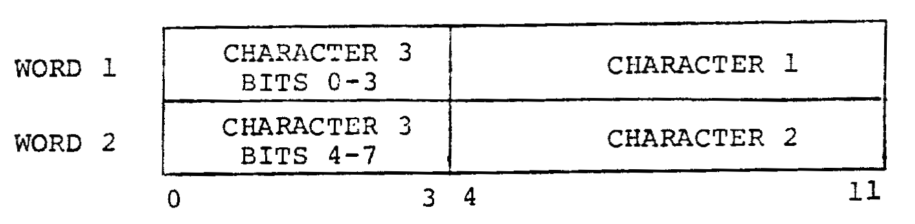
Per the comments, this function takes a buffer full of 8-bit characters and packs them into a smaller buffer where each word has 1½ characters.The comment describes this as “TSS8 format”, TSS8 being a time-sharing OS for the PDP-8.
It accepts two arguments:
A pointer to a buffer that is 0300 words long,A page and a half
containing one character per word.
A pointer to a 0200-word-long bufferone page of core
to put the packed data.
It also warns that it “uses auto index 10 and 11”, about which more later.
So given three unpacked wordsThe digits depicted here indicate character identity, not bit value: bits can only be 0 or 1!
in our input buffer:
000011111111
000022222222
000033333333
We will end up with two words packed as follows in our output buffer:
111111112222
222233333333
PCKCNT
TAD PCKBFL /-BUFFERLENGTH OUTPUTBUFFERSTLRAR/DIVIDE BY 2DCA PCKCNT
We begin by loading the value of PCKBFL, which starts at -200. We’ll be writing two words at a time, so our loop will want to divide that by two. We use RAR to take advantage of the fact that shifting bits to the right divides by 2 in the same way that shifting digits to the right divides by 10 in decimal.
But since we’re using negative values for this, we first need to make sure the LINK is set so that our value stays negative. We do this with the STL instruction, which is made up of CLLClear LINK: that is, set it to 0
and CMLComplement LINK: set it to the opposite of what it was. In this case it flips the CLL’s 0 into a 1.
You may remember that we can use OPR instructions to generate a small number of constants. In this case we use CLA CMAClear the AC and then take its ones-complement.
to load a -1 into the AC. We then add this to the first argument, resulting in the address before the start of our input buffer.
But then we store it in zero-page address 0010. This is one of the auto index locations mentioned earlier.
We then ISZ to move on to the next argument.
CMA/-1TADI PACK /ADDRESS OUPUTBUFFERDCA11ISZ PACK
WE do the same thing for the output buffer, but since we recently did a DCA we know we don’t need to CLA: the AC is already 0.
We store the address before the output buffer in auto-index address 0011.
Autoindexing
PCKLOP,TADI10/GET CHAR
The PDP12 System Reference has the following to say about autoindexing:
The eight registers in locations 10-17 of Page 0 have a special function when indirectly addressed. The contents of such a register are first incremented by 1; the result is taken as the effective address of the operand. This autoindexing feature allows the programmer to address a series of contiguous locations without extra address modification…
Since we’re doing a TAD I in this instruction, the indirect addressing circuitry in the PDP-8 will increment the value at address 0010 before doing the memory-indirect addition. This is the reason we first wrote the address before our buffer: the first time we used this index, it incremented the pointer right to the start of our buffer. So now our AC has the first word in our input buffer.
Shift Left
CLLRTLRTLDCA PCKTMP /TEMP. STORAGE
Since RTL rotates left twice, we double it up to move our character four bits up to the top of our word. The CLL turns the rotate into a shift, since we know we’ll bring in zeroes on the right.
Before:
LINK: 0
AC: 000011111111
After:
LINK: 0
AC: 111111110000
We store this shifted form in PCKTMP for later.
Shift Right
TADI10/NEXT CHARRTRRTR
We do the same with the second character,Remember that address 0010 is incrementing each time we do an I instruction on it.
but this time we want to shift it right four bits:
Before:
LINK: 0
AC: 000022222222
After:
LINK: 2
AC: 222000002222
Bitwise Operations
DCA PCKTP1TAD PCKTP1AND C17TAD PCKTMPDCAI11/FIRST WORD
We store a copy to our second temporary variable, PCKTP1 and re-load it to AND with C17, which is just the constant 0017000000001111 binary
. This reduces our AC to just the four least-significant bits, which now hold the four most-significant bits of our second character.
Since we’ve taken great care that we have zeroes for the eight most-significant bits of our AC, and that we had zeroes in the four least-significant bits of PCKTMP, we know that we can TAD to perform a sort of OR operation and not interfere with our LINK from earlier.
To summarise:
TAD PCKTP1:
LINK: 2
AC: 222000002222
AND C17:
LINK: 2
AC: 000000002222
TAD PCKTMP:
LINK: 2
AC: 111111112222
So that’s the first 1½ characters packed! We write out the first packed word to our output buffer using autoindex register 0011 in the zero page, and move on to the next bit.
The Third Character
TAD PCKTP1 /PICK UP AGAINRARAND C7400
We pick our rotated second character back out of PCKTP1 and rotate it right one last time. We’ve not called any CLL operations or done any TAD calls that would affect the LINK, so we know it still has that remaining bit for us to pop back into place. So our operations look like this:
TAD PCKTP1:
LINK: 2
AC: 222000002222
RAR:
LINK: 2
AC: 222200000222
AND C7400:C7400 contains 7400 as you would expect, also read as 111100000000 binary.
LINK: 2
AC: 222200000000
So we’ve quickly lined up those four bits and masked off the rest to accept our third character:
TADI10/NEXT CHARDCAI11/SECOND WORD
Again, we can safely TAD without overflow or mixing, and write it straight into the next word of our output buffer as 222233333333.
Since PCKCNT uses the Negative Loop Index idiom, we keep going back up to PCKLOP until we’ve exhausted our two buffers, and return.
UNPSGL
Instead of doing the buffer-to-buffer unpack routines from this cookbook, let’s look at the subroutine that unpacks characters one at a time from the buffer:
/034 SUBROUTINE UNPACKS CHARACTERS ONE BY ONE (TSS8)/PACKED THREE CHARACTERS IN TWO WORDS (TSS8 FORMAT)/PACKED:111111112222/ 222233333333//CALL :JMS UNPSGL/ ADDRESS INPUTBUFFER/ RETURN BUFFER EMPTY AC=0/ NORMAL RETURN AC=CHAR.//INITIALIZE ONCE UNPRBF:=UNPBEF:=UNPCNT:=0//UNPSGL,0CLACLLTAD UNPRBF /ARE THERE CHARS INSZACLA/TEMP. BUFFER ?JMP UNPGET /YES, GET ONETAD UNPBEF /NO, INPUTBUFER EMPTY ?SZACLAJMP UNPEMP /YES,RETURN END OF BUFFERTAD UNPCNT /NO OR YES,MUST ISNACLA/START UP POINTERS ?JMS UNPINI /YES, PLEASE DOTAD UNPRBA /NO,JUST UNPACK NEXT WORDSDCA UNPRPTADI UNPPTR /NEXT WORD FROM INPUTBUFRTRRTRAND C377DCAI UNPRP /FIRST CHAR IN TEMP. BUFISZ UNPRPTADI UNPPTR /GET WORD AGAINCLLRTLRTLAND C360DCAI UNPRP /TEMP. STORAGEISZ UNPPTRTADI UNPPTR /NEXT WORDCLLRALRTLRTLAND C17TADI UNPRPDCAI UNPRP /SECOND CHARISZ UNPRPTADI UNPPTR /THAT WORD AGAINISZ UNPPTRAND C377DCAI UNPRP /THIRD CHARTAD UNPRBA /RESET POINTER TEMP. BUFDCA UNPRPCLACLLCMARTL/-3DCA UNPRCT /3 CHAR'S IN TEMP. BUFISZ UNPCNT /INPUTBUFFER EMPTY ?JMP UNPGET /NO,GET CHAR NOWIAC/YES,SET FLAG BUFFER EMPTYDCA UNPBEF /AND THEN GET CHARUNPGET,ISZ UNPRCT /LAST FROM TEMP. BUF ?IAC/NO,SET FLAGDCA UNPRBF /YES RESET FLAGTADI UNPRP /GET CHARISZ UNPRPISZ UNPSGL /NORMAL EXITUNPEMT,ISZ UNPSGLJMPI UNPSGL/UNPEMP,DCA UNPBEF /RESET FLAGJMP UNPEMT /AND EMPTY BUFFER RETURN/UNPINI,0DCA UNPRBF /RESET FLAGTADI UNPSGL /ADDRESS INPUTBUFFERDCA UNPPTRTAD UNPBFL /-LENGTH OF BUFFERSTLRAR/DIVIDE BY 2DCA UNPCNTJMPI UNPINI//VARIABLESUNPBFL,-400UNPCNT,0UNPRCT,0UNPRP,0UNPPTR,0UNPRBF,0UNPBEF,0UNPRBA,UNPRBUNPRB,000//GENERAL CONSTANTSC17,17C360,360C377,377
Arguments
This subroutine takes one argument, which is the address of the input buffer. But it also needs you to specify a callback instruction that gets executed if the return buffer is empty.
So you might call it like this:
JMS UNPSGL0260/ ADDRESS OF RDBLK STORAGEJMP RDBLK / READ ANOTHER DISK BLOCK INTO 0260TYPE/ PRINT AC
Underflow Check
The code warns us that its internal variables UNPRBF, UNPBEF, and UNPCNT should be reset to 0 each time we try a new input buffer. The names are terse and confusing, so here’s what you need to know:
UNPRBF:
This is a Read Buffer Flag, and is nonzero when there are unpacked characters waiting to be read and returned.
UNPBEF:
This is a Buffer Empty Flag, and is set when the input buffer has run out of packed words.
UNPCNT:
This is a countdown index showing how many more words we have left to read from the input buffer.
CLACLLTAD UNPRBF /ARE THERE CHARS INSZACLA/TEMP. BUFFER ?JMP UNPGET /YES, GET ONE
The beginning of this function has a lot of catching up to do. It asks a lot of questions about what may or may not have happened in previous invocations.
In this case, it’s trying to see if we still have chars in our little temporary buffer. If it’s 0, we skip over the UNPGET jump and keep testing things with a freshly-cleared AC.
TAD UNPBEF /NO, INPUTBUFER EMPTY ?SZACLAJMP UNPEMP /YES,RETURN END OF BUFFER
To start with we set up UNPBEF as 0, so we’ll skip the jump to the UNPEMP section now and keep going.
TAD UNPCNT /NO OR YES,MUST ISNACLA/START UP POINTERS ?JMS UNPINI /YES, PLEASE DO
If we’ve reached this point, we don’t have anything in our read buffer and our input buffer isn’t empty, so we check the UNPCNT to see if we have a countdown going. If so, we skip on non-zeroAC and keep going.
But in our case, everything’s 0 so we need to run a subroutine from our subroutine.Presumably we hit this condition every three characters.
Lets dive down into that, shall we?
JMS UNPINI
UNPINI,0DCA UNPRBF /RESET FLAGTADI UNPSGL /ADDRESS INPUTBUFFERDCA UNPPTRTAD UNPBFL /-LENGTH OF BUFFERSTLRAR/DIVIDE BY 2DCA UNPCNTJMPI UNPINI
We came here from a TAD UNPCNT, so we store that in UNPRBF. That’s still 0 for now, so nothing has changed yet.
Next we read the address of the input buffer from the argument space and store it in UNPPTR. We don’t ISZ past that until the end of the code, as there are multiple branches where it gets read.
Then we read the negative length of the buffer from UNPBFL and do the same STL RAR trick as before to divide it by two. Since our buffer is 400 (256 decimal) words long,This is a standard block size for storage media of this era. LINCTape, DECTape, and the RS and RK models of disk drives all serve up 256 blocks of 12-bit words to PDP-8 systems.
we end up with -200, which we finally store in UNPCNT.
So UNPCNT will keep track of how far we are through one disk or tape block of packed data.
Let’s return from UNPINI and resume UNPSGL.
Unpacking Character One
TAD UNPRBA /NO,JUST UNPACK NEXT WORDSDCA UNPRP
UNPRBA has the address of UNPRB in it, which is a three-word buffer defined at the end of our routine.
TADI UNPPTR /NEXT WORD FROM INPUTBUFRTRRTRAND C377DCAI UNPRP /FIRST CHAR IN TEMP. BUF
We read a packed word, rotate it right four place values, and mask off 000011111111 to keep the eight least-significant bits that now hold our character. Then we write that straight into the first location in UNPRB. Let’s write that as UNPRB1.
Unpacking and Reassembling Character 2
ISZ UNPRPTADI UNPPTR /GET WORD AGAINCLLRTLRTLAND C360DCAI UNPRP /TEMP. STORAGE
Now we increment UNPRP to point to UNPRB2 and re-read that first word. Now we shift this left four spaces and mask off 000011110000 to get the half-character in the right place. We store that in UNPRB2 and keep going.
This time we increment UNPPTR and read in the next word. We leave UNPRP alone, because we’re not finished assembling UNPRB2 yet.
We rotate five times left to get our four bits past the LINK and into the four least-significant bits of the AC, and mask off 000000001111 to get the second half of character 2. We add it to UNPRB2 and write it back there again, complete.
Finally we advance UNPRP to start working on UNPRB3 and re-load the second word from our input buffer. This is a simple matter of masking off 000011111111 and storing in UNPRB3.
So that’s three characters unpacked. What now?
Preparing to Return Single Characters
If you recall, our subroutine doesn’t return a pointer to a buffer: it returns one character each time it’s called. So we need to hang onto our three-word UNPRB buffer and return bits of it as needed.
TAD UNPRBA /RESET POINTER TEMP. BUFDCA UNPRPCLACLLCMARTL/-3DCA UNPRCT /3 CHAR'S IN TEMP. BUF
First, we point our UNPRP back to the start of the three-character buffer, and set up UNPRCT with a -3 to start the countdown indexing into it.This rather clever CLA CLL CMA RTL instruction is explained somewhat in the OPR section of this document.
ISZ UNPCNT /INPUTBUFFER EMPTY ?JMP UNPGET /NO,GET CHAR NOW
If we still have buffer to get through, then it’s time to get and return one of our characters.
JMP UNPGET
UNPGET,ISZ UNPRCT /LAST FROM TEMP. BUF ?IAC/NO,SET FLAGDCA UNPRBF /YES RESET FLAG
We haven’t reached the end of our buffer yet, so we don’t skip the IAC instruction. That means we increment the AC to 1 before writing it out to UNPRBF. So the flag is still showing this read buffer as ready.
We load our character into the AC and increment UNPRP to UNPRB2. We then hit the UNPSGL parameter-handling logic.
Since we got this far, we’re returning a character in the AC. So we advance the UNPSGL pointer past both the input buffer pointer and the “return buffer empty” handler instruction.
Second Call
OK, so we’ve done a lot of unpacking work to get three characters, but we’ve only returned UNPRB1 so far. What about the other two? Let’s see what happens the second time we call UNPSGL.
TAD UNPRBF /ARE THERE CHARS INSZACLA/TEMP. BUFFER ?JMP UNPGET /YES, GET ONE
The first thing we hit in this function is a test of UNPRBF, which sends us back to UNPGET. So we skip all of the unpacking instructions and come back here:
UNPRCT is -2 when we enter this, and demoting to -1 isn’t enough to skip the increment of UNPRBF back to 1. We load UNPRB2 into the AC and advance UNPRP to UNPRB3 for next time. Then we return back to the “character in AC address” from the caller.
Third Call
We haven’t cleared UNPRBF yet, so we’re back in UNPGET.
This time when we increment UNPRCT from -1 to 0 we skip the IAC and end up storing a 0 into UNPRBF. We load UNPRB3 and advance UNPRP past the end into invalid memory before returning normally.
Fourth Character
Let’s assume we’ve been successfully reading triplets of characters for a while, and have just finished as before but now we’re out of input buffer.
CLACLLTAD UNPRBF /ARE THERE CHARS INSZACLA/TEMP. BUFFER ?JMP UNPGET /YES, GET ONETAD UNPBEF /NO, INPUTBUFER EMPTY ?SZACLAJMP UNPEMP /YES,RETURN END OF BUFFERTAD UNPCNT /NO OR YES,MUST ISNACLA/START UP POINTERS ?JMS UNPINI /YES, PLEASE DOTAD UNPRBA /NO,JUST UNPACK NEXT WORDS
If UNPRBF is 0 because we’ve finished three characters, and UNPBEF is still 0 because our input buffer still holds data, then we load UNPCNT and skip the initialisation and go straight to the unpacking instructions.
Buffer Empty
But if UNPBEF had been incremented by the unpacking code reaching the end, then we’d jump to UNPEMP:
When we arrive this way, we only increment the return pointer for UNPSGLonce past the input buffer argument. So when we return, we’re returning to the instruction that indicates the buffer was empty. This lets you JMP or ISZ some flag somewhere to let the rest of your code determine what to do.
PACKB
This function appears in Volume 2 of the Cookbook, and is credited to Adri Hemelaar at the same institute where Floor worked. By this point, PDP-8 hardware allowing more than the basic 4k words of RAM was more available, and OS/8 was solidifying as a popular standard.
OS/8 packed byte streams from teletype devices (such as paper tape readers) for its own input buffers, but in a different layout to the previous examples. Bytes 1 and 2 would occupy their normal spaces in a pair of 12-bit words, but the remaining space would be used to store 4-bit “nybbles” of the third byte.
/ PACK A CHARACTER IN A BUFFER IN OS/8 FORMAT/ CAN BE USED FOR BUFFERS UP TO 31 PAGES/ (NOT USING LAST PAGE OF FIELD)/ PARAMETERS ARE:/ CURFLD: FIELD OF SUBROUTINE/ BUFFLD: FIELD OF BUFFER/ BUFBEG, BUFEND: DEFINE SIZE OF BUFFER/ CALL: TAD CHAR/ JMS PACKB/ BUFFER FULL RETURN(AC=0)/ NORMAL RETURN (AC=0)0/TEMPORARY STORAGEPACKB, .-.DCA PACKB-1/SAVE CHARACTERTAD PACKSW /TEST PACKSWITCHCDF BUFFLDSZAJMP PACKB1 /IF -2TAD PACKB-1/GET CHARACTERDCAI PACPTR /INSERT IN BUFFERTAD PACPTRCLLRAR/IS POINTER ODD?SNLCLA/SKIP IF YESJMP.+4CLACLLCMARAL/SET PACKSWITCH TO -2DCA PACKSWSKPISZ PACPTR /INCREMENT POINTER IF EVENJMP PACKB2 /GO TO EXITPACKB1,CLACLLCMATAD PACPTR /DECREMENT POINTERDCA PACPTRTAD PACKB-1/GET CHARACTERRTLRTL/SHIFT 4 POSITIONS TO LEFTDCA PACKB-1/SAVE TEMPORARYTAD PACKB-1AND C7400 /KILL BITS 4-11TADI PACPTRDCAI PACPTR /INSERT IN BUFFERISZ PACPTR /INCREMENT ADDRESS POINTERISZ PACKSW /INCREMENT PACKSWITCHJMP PACKB1+3/AGAIN IF PACKSWITCH NONZEROTAD PACENDCMACLL/TEST FOR BUFFER ENDTAD PACPTRSNLCLA/SKIP IF FULLJMP PACKB2TAD PACBEG /INITIALIZE POINTERDCA PACPTRSKPPACKB2,ISZ PACKB /NORMAL RETURNCDF CURFLDJMPI PACKBPACPTR,BUFBEGPACKSW,0PACBEG,BUFBEGPACEND,BUFENDC7400,7400
Parameters
This function dispenses with the TAD I/DCA/ISZ pattern of copying parameters in. Instead, it assumes that the input parameters are defined as symbols somewhere in your code as global values.
It accepts a character in the AC, and lands you at the following instruction if the buffer is full or the one after if everything’s normal.
Memory
First of all, this code uses .-. as the idiom for the return pointer placeholder value. This is a visually distinct way to highlight a subroutine definition.This works because . expands to the current instruction address, and subtracting that from itself gets us a zero.
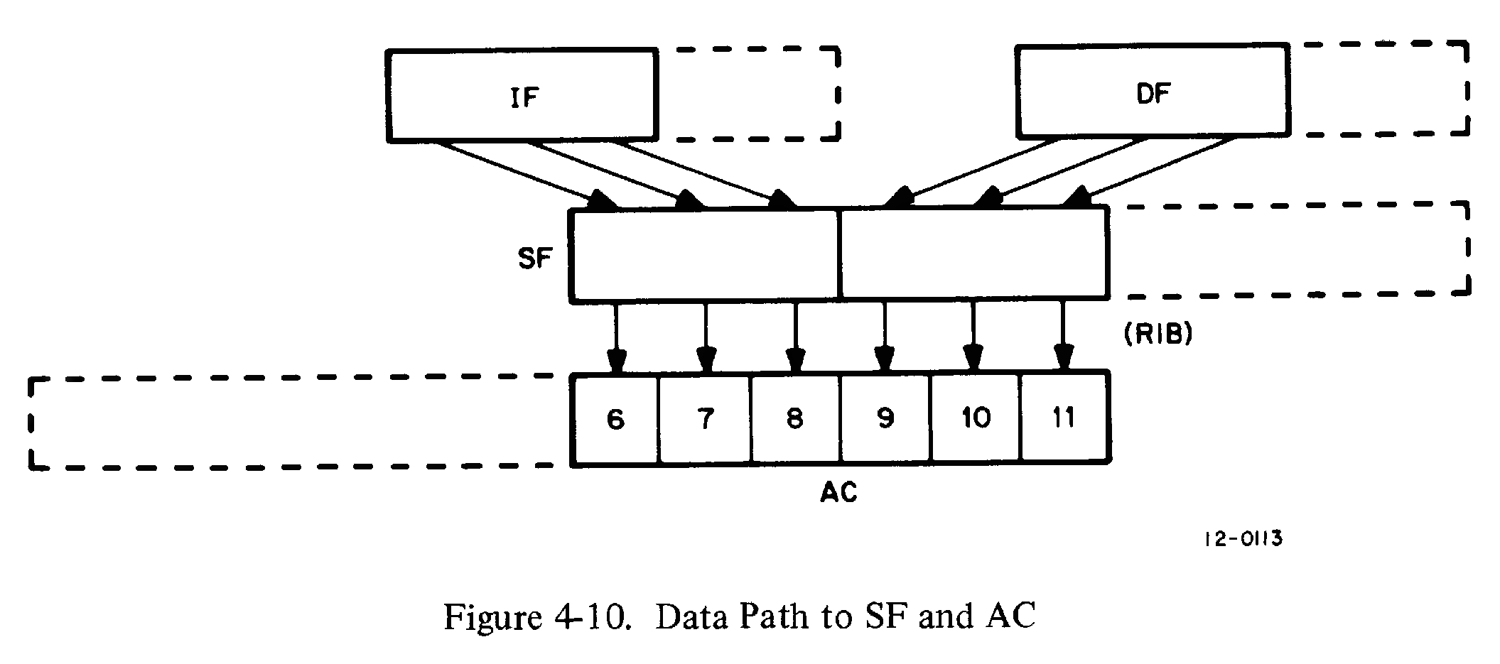
The first instruction seems normal, saving the AC parameter in our temporary storage, but what is this CDF instruction? Let’s consult the PDP-12 System Reference about Extended memory:
When additional 4096-word memory banks are attached to the PDP-12, the Memory Extension Control provides access to the additional storage, both for programs and data. The registers of the Control are already built into the PDP-12…
Instruction Field Register (IF), 3 Bits
These three bits serve as an extension of the PC for determining the 4096-word field from which executable instructions are to be taken. All direct memory references are made to registers in the Instruction Field. With one exception, all JMP and JMS instructions, whether direct or indirect, are to registers within the Instruction Field. The exception is the first JMP or JMS executed after a CIF instruction is given. This causes the field to change.
Data Field Register (DF), 3 bits
These three bits serve as an extension of the Memory Address register for determining which memory field contains the operands to be accessed by the memory reference instructions AND, TAD, DCA, and ISZ when indirect addressing is used. The Data Field and Instruction Field may be set to the same field.
Memory Field Instructions
Mnemonic
Octal
Effect
CDF
62n1
The quantity n is transferred to the Data Field register. All subsequent indirect memory references by AND, TAD, ISZ, and DCA are to the new field.
CIF
62n2
The quantity n is transferred to the Instruction Field Buffer. At the occurrence of the next JMP or JMS instruction, whether direct or indirect, the contents of the IB are transferred to the IF. The effective address of the jump is placed in the PC, and the program continues from that address in the new Instruction Field.
RDF
6214
The contents of the Data Field register are ORed into AC6-8. The other bits of the AC are unaffected.
RIF
6224
The contents of the Instruction Field register are ORed into AC6-8. The other bits of the AC are unaffected.
RIB
6234
The contents of the Save Field register are transferred to the AC as follows: Bits 0-2 (IF) are ORed into AC6-8; bits 3-5 (DF) are ORed into AC9-11.
RMF
6244
The contents of the Save Field register are placed in the Instruction Field Buffer and DF as follows: Bits 0-2 (original Instruction Field) are transferred to the IB; bits 3-5 (original Data Field) are restored to the Data Field register.
To make a long story short, these field registers let us switch among 8 “fields” of 4096 words of core, for code or memory-indirect data, or both.
So by changing our field to BUFFLD, which presumably is a 4096-word field of memory set aside for OS/8 buffer data, we change the AND I, TAD I, DCA I, and ISZ I instructions to use that field instead of the current one.
Pack Switch
That was a lot to get into, so here’s a bit of retread:
TAD PACKSW /TEST PACKSWITCHCDF BUFFLDSZAJMP PACKB1 /IF -2TAD PACKB-1/GET CHARACTERDCAI PACPTR /INSERT IN BUFFER
So in order, we:
Read PACKSW into the AC
Change the memory-indirect data field to BUFFLD
Skip the JMP PACKB1 if PACKSW was 0
Load our character from temporary storage
Store it at PACPTR over in that BUFFLD field, thanks to the effect CDF had on DCA I.
So right out of the gate, we’ve written a character to the first word of our buffer, as PACPTR starts out as BUFBEG.
First Character
TAD PACPTRCLLRAR/IS POINTER ODD?SNLCLA/SKIP IF YESJMP.+4CLACLLCMARAL/SET PACKSWITCH TO -2DCA PACKSWSKPISZ PACPTR /INCREMENT POINTER IF EVENJMP PACKB2 /GO TO EXIT
But now that we’ve written this, we check to see if the destination was odd or even. We’ve seen that the way we pack three 8-bit values into two 12-bit words has an alternating pattern.
If the PACPTR is even, we fall through to the JMP .+4 which increments PACPTR to an odd number and jumps to the exit code:
This advances the return pointer to the normal return instruction in the calling code, and restores the DF to CURFLD before JMPing back.
Second Character
But the next time through, PACKSW is still 0 but PACPTR is odd. That means it now runs this:
CLACLLCMARAL/SET PACKSWITCH TO -2DCA PACKSWSKPISZ PACPTR /INCREMENT POINTER IF EVEN
It sets PACKSW to -2 and skips the increment of PACPTR, keeping it an odd address. So now we’ve written a character in BUFBEG and another in BUFBEG+1. So far this isn’t very well packed, so let’s see what happens the third time.
And now we go back with the second word and write the four least-significant bits to the left of our second character. So our words now look like:
333311111111
333322222222
This is the OS/8 format, so we’re done packing.
Empty Buffers
TAD PACENDCMACLL/TEST FOR BUFFER ENDTAD PACPTRSNLCLA/SKIP IF FULLJMP PACKB2TAD PACBEG /INITIALIZE POINTERDCA PACPTRSKPPACKB2,ISZ PACKB /NORMAL RETURNCDF CURFLDJMPI PACKB
We subtract PACEND from PACPTR and JMP to the normal exit if the result is still negative. Otherwise, we reset PACPTR to PACBEG and skip the “normal” return so that we JMP back to the buffer-full-handling instruction in the original code.
UNPACK
/UNPACK CHAR BY CHAR FOR OS8 HANDLERS./ROUTINE UNPACKS AN OS8 FORMAT ASCII BUFFER CHARACTER/BY CHARACTER. IT NEEDS A POINTER (CA) SET TO THE/BEGINNING OF THE BUFFER, AND A WORDCOUNT (WC) SET/TO - THE NUMBER OF WORDS IN THE BUFFER -1./THE LOCATION 'SETCDF' NEEDS TO BE SET TO THE FIELD/WHERE THE BUFFER RESIDES./THE PACKSWITCH HAS 3 VALUES:0 FOR THE FIRST OF 3 CHARS./1 FOR THE SECOND, AND 2 FOR THE 3RD./THE PACKSWITCH SHOULD BE 0 WHEN ENTERED FOR THE FIRST/TIME. THE ROUTINE LEAVES THE DATAFIELD TO THE FIELD/OF BUFFER UPON EXIT. IF BUF EMPTY THEN JUMP TO 'XIT'.PACKSW,0/0,1,OR 27400377UNPACK, .-. /ENTER WITH AC=0SETCDF,CDF/OVERLAIDTAD PACKSWRARSZL/1?JMP UNP2 /YSZACLAJMP UNP3 /2UNP1,TADI CAAND UNPACK-2CLLRTRDCA TEM /BYTE 3 ALREADY PARTLY PREPAREDTADI CAAND UNPACK-1ISZ CAISZ PACKSWISZ WC /INCR. TWICE, EVERY 3 BYTESJMPI UNPACKC7600,7600/CLAJMP XITUNP2,TADI CAAND UNPACK-2/PREPARE 3RD BYTECLLRTRRTRRTRTAD TEMJMP UNP1+2UNP3,DCA PACKSW /PREPARE FOR NEXT ENTRYTAD TEMJMPI UNPACKTEM,0/SOMEWHERE IN THE HANDLERCA,0WC,0
 Modern practice is to call the least-significant bit “0” and count up as we move left. For some reason, Digital always counted in the other direction. Take care when interpreting bit numbers described in DEC manuals!
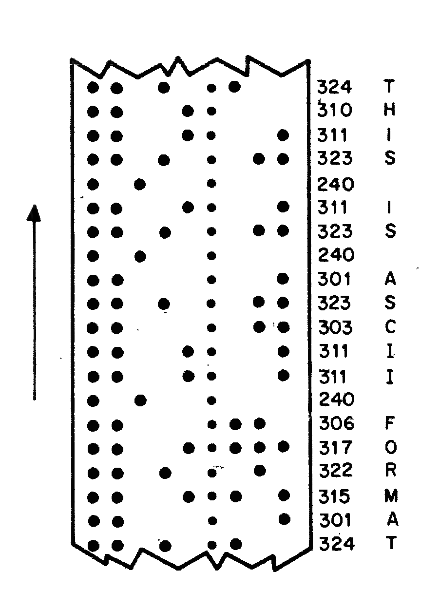
Comments
In PAL, the standard PDP-8 assembler, everything following a
/is a comment. Floor began this section with the entry number (001) and a brief description of how to use this subroutine. Following that, he gave some example codeComplete with explanatory comments-within-comments!so you can see how this might be used:
JMSinstruction to callTYPTEX.0in your code.ACCUMULATORACfor short.will be set to
0whenTYPTEXreturns.So let’s start with each of these parts in turn: